Project 3
RGB LED Wizard
By Gavin Nguyen
Overview
In this project, you will program an ESP32 to control a dimmable RGB light! At each checkpoint, you will explore the core functions of microcontrollers: digital input/output, pulse width modulation, and analog-to-digital conversion.
Concepts
ESP32
The ESP32-C3Fx4 is a board based on an ESP32 microcontroller. It is hobbyist-friendly and was developed by WeAct Studio: they added a USB-C port, voltage regulator, and an onboard LED (among other things).The chip itself contains the processor, RAM, and flash storage. These components execute the programs we write, which allows us to build and control cool projects with them!
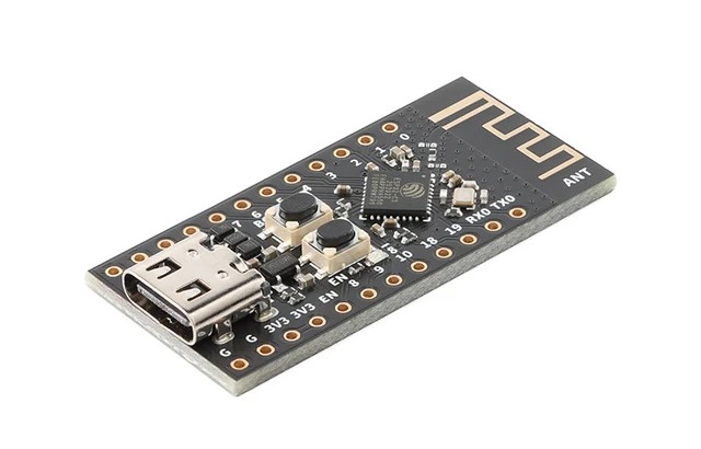
In OPS, we will refer to the ESP32-C3Fx4 board as an ESP32 from now on for convenience. The ESP32 board is depicted here (without its pin headers).
General Purpose Input/Output (GPIO) pins, power, and ground pins run along the sides of the ESP32.
In the lecture content, we discuss the different GPIO pin capabilities and their use cases. To program the ESP32, we will use the Arduino programming language (a C++ variant) to write and compile sketches. Learn more here.
We won't talk in depth about each function or data structure from the Arduino Library. When you need to read up on Arduino code, refer to the Arduino Language Reference.
ESP32 Guide (IMPORTANT)
Before moving forward, it is crucial that you follow the steps in our ESP32 Guide to set up and learn how to program the ESP32. Visit the ESP32 Guide here or by clicking "ESP32 Guide" on the top navigation bar.
Pinout
Thinking about using a pin but you don't know what it does? Refer to the ESP32 Board pinout diagram.
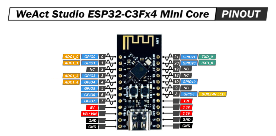
- NC stands for No Connect, and these pins should be left unconnected at all times.
- GPIO stands for a General Purpose Input/Output pin and can be used to send or read signals.
- The ~ symbol represents pins that are PWM (Pulse Width Modulation) capable.
RGB LED
For this project, we will use a common cathode RGB LED. Inside this component are three smaller LEDs - one red, one green, and one blue. They are all connected by a shared or common cathode.
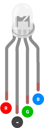
This RGB LED has four pins: One is the common cathode, and the other three are the red, green, and blue LED anodes.
Using it in Arduino IDE
In the world of digital electronics, color is often represented in the 8-bit RGB color model.
Every
visible color is
identified by an encoding of the three base colors: red, green, and blue. In our Arduino code,
we
will set the
intensity of each base color to a value in the range 0-255.
Try the RGB Color Picker. Adjust the slider at the bottom of the application. Notice how the three values in the RGB field change as you select different colors.
Recall that LEDs are current driven: we control the intensity of each RGB LED color by increasing/decreasing the current passing through its pin. With the ESP32 board, we set the voltage, which changes current flow (recall Ohm's Law).
Here's the rub: digitalWrite() can only set a
pin's
voltage to 0 or 3.3V (the supply voltage). If we want to dim an LED, we need a new function that
can
output voltages between 0 and 3.3.
We will use a pulse width modulation or PWM signal - a digital
waveform mimicking
analog voltage signals. With PWM
waves, we can generate analog voltages like 1.3V or 2.1V. In Arduino, we accomplish this using
analogWrite().
Potentiometer
A potentiometer is a three-terminal variable resistor. We will use it as a voltage divider, a circuit which accepts a supply voltage and outputs a voltage which is a fraction of the supply voltage. The voltage of the potentiometer's output pin ranges between the VCC and GND pin voltages, depending on the dial's position.
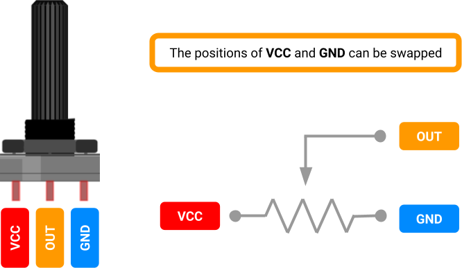
How it Works
We just referred to the potentiometer as a kind of resistor. Why? Internally, a resistive strip connects its VCC and GND pins, and a rotating wiper connects the output pin to the strip. The greater the distance along the strip between the wiper and the VCC pin, the greater the resistance between the wiper and VCC.
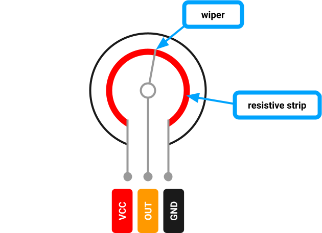
In this voltage divider configuration, the wiper reduces the voltage at the output pin the further it is turned in a direction.
Using it with ESP32
We can connect the potentiometer's output pin to one of the ESP32's ADC pins (see its pinout
above).
The ADC pin is wired to the analog-to-digital converter (ADC)
inside the ESP32-C3 chip. The ADC is hardware that translates the analog signal to a discrete
digital signal. Using
analogRead(), we interpret the pin's analog voltage as
a
discrete integer in the range 0-4095.
Requirements
LED Blinker
- You must build a blinking LED circuit.
- The LED in the circuit must blink once per second.
- The LED must be brightly lit when turned ON.
- The LED must be completely dark when turned OFF.
- The circuit must be built on a breadboard.
LED Dimmer
- You must build a circuit with a dimmable LED.
- The user must be able to adjust the LED's brightness from 0% to 100% when turning the potentiometer dial.
- When turning the potentiometer one way, the LED should brighten.
- When turning the potentiometer the other way, the LED should dim.
- The circuit must be built on a breadboard.
RGB LED Wizard
- You must build a circuit with a dimmable RGB LED.
- The user must be able to adjust the RGB LED to any color when turning the three potentiometer dials.
- Each potentiometer should control the light intensity of one of the three LED colors (red, green, and blue).
- When turning a potentiometer one way, its respective LED color should brighten.
- When turning a potentiometer the other way, its respective LED color should dim.
- The circuit must be built on a breadboard.
Parts
| Part Name | Qty |
|---|---|
| Jumper Wire | X? |
| Breadboard | 1 |
| Potentiometer, 10kΩ | 1 |
| LED, 2V | 1 |
| LED, RGB, Common Cathode | 1 |
| ESP32 | 1 |
| Resistor, 220Ω | 1 |
| Resistor, 390Ω | 3 |
| USB-A to USB-C Cable | 1 |
Schematics


Instructions
Checkpoint 1
-
Build the circuit from Schematic A (LED Blinker) on your breadboard. You will
design a blinking LED using the ESP32.
Use the pseudo code below to program an LED that blinks on and off.These functions may be helpful:
Serial.begin(),pinMode(),digitalWrite(),delay()// Assign variable to pin number for LED void setup() { // Configure LED pin's behavior to OUTPUT // Configure the Serial baud rate to 115200 } void loop() { // Set LED pin to HIGH // Delay // Set LED pin to LOW // Delay } - Upload your sketch to the ESP32, and verify that the program executes as expected; the LED should cycle ON and OFF.
Checkpoint 2
-
Build the circuit from Schematic B (LED Dimmer) on your breadboard. Your goal
is to make the LED grow brighter as you twist the potentiometer one way and dimmer the other way.
Use the pseudo code below to program the circuit.These functions may be helpful:
Serial.begin(),pinMode(),analogRead(),analogWrite()// Assign variable to pin number for LED // Assign variable to pin number for Potentiometer void setup() { // Configure the LED pin's behavior to OUTPUT // Configure the Potentiometer's pin behavior to INPUT // Configure the Serial baud rate to 115200 } void loop() { // Read potentiometer pin value // Set LED pin to the potentiometer pin value } - Upload your sketch to the ESP32, and verify that the circuit meets the design requirements.
Checkpoint 3
- Build the circuit from Schematic C (RGB LED Dimmer) on your breadboard. No pseudo code this time! You are on your own.
- Upload your sketch to the ESP32, and verify that the circuit meets the design requirements.
Deliverables (Enrolled Students Only)
Students enrolled in the course must submit the following deliverables to the corresponding Canvas course assignment.
Place the following files in a single folder:
-
Video of the RGB LED Dimmer (Schematic C) on a breadboard
In the video, use the potentiometers to create the colors yellow, green, and cyan.Compress the folder to a zip file and rename the file using the format “ops_project#_lastname_firstname.zip” Then, submit the zip file to the Project 3 Canvas assignment.