Project 4
Ultrasonic Trashcan
By Patrick Cabanban
Overview
You will program an ESP32 to control a servo with various sensors and inputs. At each checkpoint, you will explore the core functions of servos and ultrasonic distance sensors. You will also get more practice with microcontrollers (digital input/output, pulse width modulation, and analog-to-digital conversion) and potentiometers.
Concepts
ESP32 Guide
It is crucial that you have followed the steps in our ESP32 Guide to set up and learn how to program the ESP32. Visit the ESP32 Guide here or by clicking "ESP32 Guide" on the top navigation bar.
Pinout
Thinking about using a pin but you don't know what it does? Refer to the ESP32 Board pinout diagram.
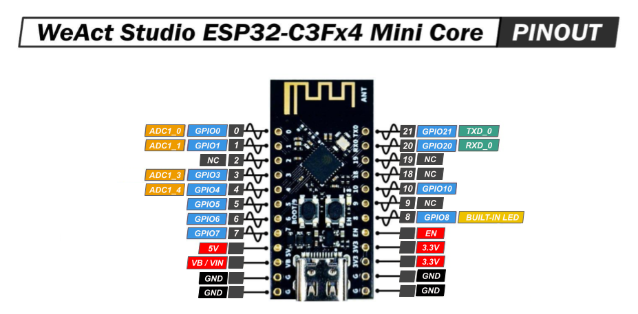
- NC stands for No Connect, and these pins should be left unconnected at all times.
- GPIO stands for a General Purpose Input/Output pin and can be used to send or read signals.
- ADC stands for analog-to-digital converter and it reads the input voltage and makes a digital number to represent that amount of voltage.
- The ~ symbol represents pins that are PWM (Pulse Width Modulation) capable.
Ultrasonic Sensor
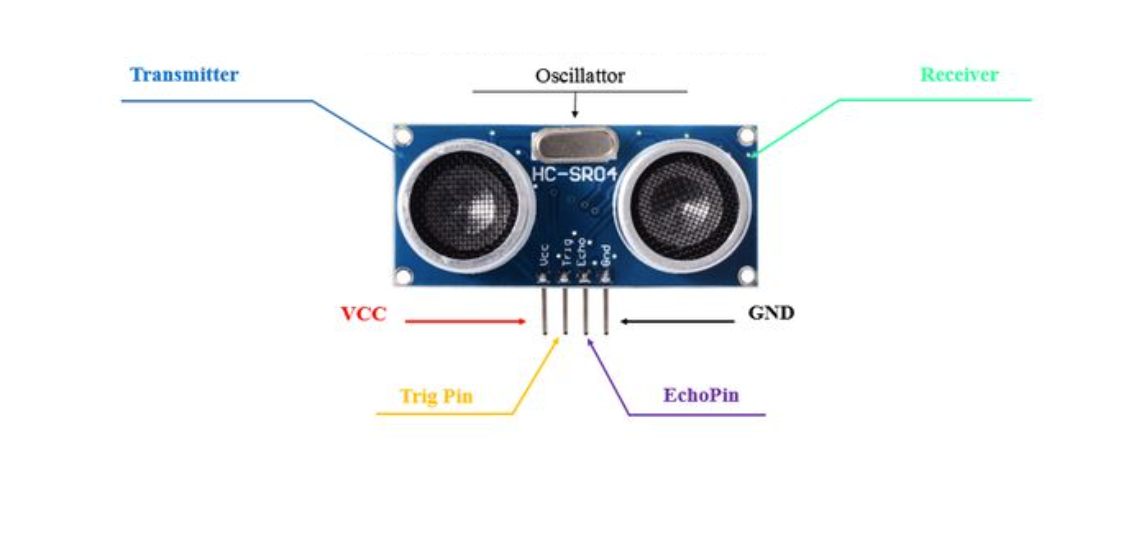
The ultrasonic sensor module (commonly the HC-SR04 )is a distance-measuring device widely used in embedded systems. It works by emitting an ultrasonic sound wave (at around 40 kHz) from its trigger (TRIG) pin and then listening for the echo reflected off nearby objects using its echo (ECHO) pin. The time it takes for the sound wave to return is measured by the microcontroller, which is used to calculate the distance using the formula:

A demo of using our provided ultrasonic sensor is found below:
-
Trig pinis in charge of sending a signal to the ultrasonic sensor to emit a burst of ultrasonic sound waves -
Echo pinis in charge of being pulled to HIGH for the same duration equal to the time it takes the ultrasonic pulse to reach a surface and return to the sensor. -
pulseInmeasures how long the ECHO pin was set high -
Delayensures that the trig pulse is a burst
const int trigPin = 3;
const int echoPin = 4;

void setup() {
  Serial.begin(115200);
  pinMode(trigPin, OUTPUT);
  pinMode(echoPin, INPUT);
}


void loop() {
	// Trigger pulse
  digitalWrite(trigPin, LOW);
  delayMicroseconds(100);
  digitalWrite(trigPin, HIGH);
  delayMicroseconds(100);
  digitalWrite(trigPin, LOW);

  long duration = pulseIn(echoPin, HIGH);  // Takes measurement of pulse in microseconds
  long distance = duration / 58.0;         // conversion to cm
  Serial.println(“Distance: “ + distance);
  delay(1000);
}
Note that the material and the angle of the object the wave is bouncing off matter for how effectively the echo pin can receive the signal. Materials like sponges or even your hand aren’t great at reflecting the waves.
Using it with ESP32
The ultrasonic sensor is actually rated for 5V, which means it is advised to use a voltage divider network on
the GPIO pins that it connects to. This is because constant 5V exposure to the ESP32
Servo
A servo motor is a type of motor that converts electrical energy into mechanical energy to achieve precise control. As seen in the image below, various arms can be attached to the splined gear on the top of the motor for different functions. In this project, you will be controlling the position of the servo with an ultrasonic sensor to make a trashcan.
The micro servo we will be using has a rating of “9g”. This represents the torque of the motor, or how much force it can apply. In the case of the servo above, it can generate 9 grams of force when 1 centimeter away from the shaft/center of the motor. The force is proportional to the distance, so the motor can support a torque of 4.5 g when 2 cm away from the shaft, 3 g when 3 cm away, and so on.
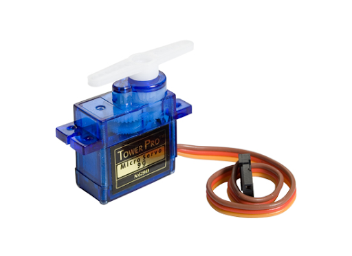
As shown in the image above, the servo motor has three different wires; the power (red), ground (brown), and pulse-width modulation (orange) wires. The power and ground wires are used to supply the servo motor with power, while the pulse-width modulation (PWM) wire is used to feed a varying PWM signal that determines the servo's position.
A demo of using out provided servo is found below:
-
Servo your_servo_nameis used to initialize the physical servo object in your code. Keep in mind that you can name your servo to whatever you’d like. -
your_servo_name.attach(int servoPin)attaches the servo object to a pin with min max values to set the axis of rotation -
your_servo_name.write()can be used to set the servo to any angle between0-180
#include <ESP32Servo.h>

// Assign variable to pin number of Servo’s PWM pin
int servoPin = 10;


// Initialize servo object with name myServo
Servo myServo;


void setup() {
	// Attach object myServo to the physical servo
	myServo.attach(servoPin);
}


void loop() {
	// Writes a 0 degree angle to the servo
	myServo.write(0);
	delay(1000);
	// Writes a 90 degree angle to the servo
	myServo.write(90);
	delay(1000);
	// Writes a 180 degree angle to the servo
	myServo.write(180);
	delay(1000);
}
Potentiometer
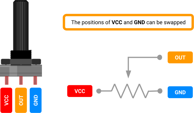
A potentiometer is a three-terminal variable resistor. We will use it as a voltage divider, a circuit which accepts a supply voltage and outputs a voltage which is a fraction of the supply voltage. The voltage of the potentiometer's output pin ranges between the VCC and GND pin voltages, depending on the dial's position.
How it Works
We just referred to the potentiometer as a kind of resistor. Why? Internally, a resistive strip connects its VCC and GND pins, and a rotating wiper connects the output pin to the strip. The greater the distance along the strip between the wiper and the VCC pin, the greater the resistance between the wiper and VCC.
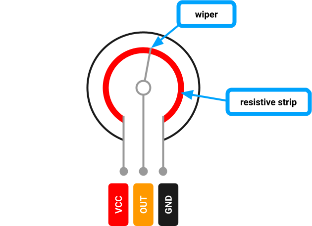
In this voltage divider configuration, the wiper reduces the voltage at the output pin the further it is turned clockwise (toward GND).
Using it with ESP32
We can connect the potentiometer's output pin to one of the ESP32's ADC pins (see its pinout
above).
The ADC pin is wired to the analog-to-digital converter (ADC)
inside the ESP32-C3 chip. The ADC is hardware that translates the analog signal to a discrete
digital signal. Using
analogRead(), we interpret the pin's analog voltage as
a
discrete integer in the range 0-4095.
Box Assembly
To assemble the trashcan, you must attach the servo to the backside of the box, configuring the servo’s angle to optimally close and open the flap. To do this, set the servo’s angle to its most extended position, that being either 0° or 180°, depending on the side that the servo is oriented.
Grab strong adhesive tape, which can be borrowed from the lab, and tape the servo down with both a horizontal strip of tape and a vertical strip. If you mess up, don’t worry! The box’s surface will not tear off with the tape if you want to reposition the tape.
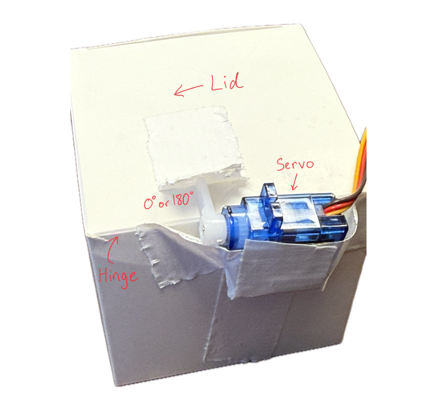
Once the servo is taped down, you must handle the ultrasonic sensor. Using the mount found in your OPS kit, place the ultrasonic sensor with the pins pointing away from the mount’s base. Slide the base under the trash can, and the project is now ready for testing!
Software Installations
Servo Library
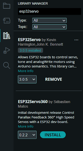
To download the servo library, click on the Library manager icon on the left panel of Arduino IDE, and type in “ESP32Servo.” The first result made by Kevin Harrington, John K. Bennett is the library we will be using to control the servo. Download the latest version of the arduino library and then you should be able to use the library’s already developed functions.
Requirements
Potentiometer-Controlled Servo
- You must build a circuit with a potentiometer that can control a servo.
- The user must be able to adjust the servo’s angle to any angle between 0-180° when turning a singular potentiometer dial.
- When turning a potentiometer in one way, the servo should approach 180°.
- When turning a potentiometer the other way, the servo should approach 0°.
- The circuit must be built on a breadboard.
Ultrasonic Sensor Trashcan
- You must build a circuit with an ultrasonic-controlled servo.
- The servo’s angle must adjust when the detected distance threshold of the ultrasonic sensor changes.
- When an object is above the distance threshold, the angle should be 0°.
- When an object is below the distance threshold, the angle should be 90°.
- The circuit must be built on a breadboard, and the servo should be attached to the cardboard trashcan cutout provided in the OPS kit to autonomously open/close the trashcan.
Parts
| Part Name | Qty |
|---|---|
| Jumper Wire | x? |
| Breadboard | 1 |
| Cardboard Box | x1 |
| Tape | x? |
| Potentiometer, 10kΩ | 1 |
| Micro Servo | 1 |
| Ultrasonic Sensor | 1 |
| ESP32 | 1 |
| Resistor, 4.7KΩ | 1 |
| USB-A to USB-C Cable | 1 |
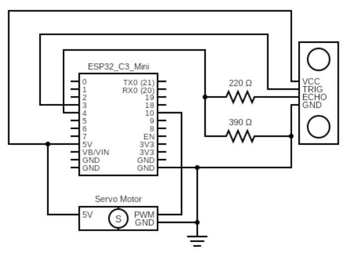
Schematics

Instructions
Checkpoint 1
-
Build the circuit from Schematic A (Potentiometer-Controlled Servo) on your breadboard.
Attach the one-sided arm attachment to the servo.
Use the pseudo code below to program a potentiometer to control a servo.These functions may be helpful:
Serial.begin(),pinMode(),analogRead(), and the servo fuctions above.#include <ESP32Servo.h> // Assign variable to pin number for Potentiometer // Assign variable to pin number of Servo’s PWM pin // Initialize servo object with your servo name void setup() { // Configure the Potentiometer's pin behavior to INPUT // Attach object of your servo name to the physical servo // Configure the Serial baud rate to 115200 } void loop() { // Read potentiometer pin value // Set and map servo angle to the potentiometer pin value } - Upload your sketch to the ESP32, and verify that the program executes as expected; the potentiometer should control the angle of the servo from 0°-180°.
Checkpoint 2
- Build the circuit from Schematic B (Trashcan) on your breadboard. Your goal is to control the servo’s angle based on the distance that the ultrasonic sensor detects thereby opening or closing the trashcan's lid.
- Tape the servo to the box as shown in the instructions above
-
Use the pseudo code below to program the circuit.Depending on your servo configuration, the values of your open and close angles may vary, however one should be high and one low. These functions may be helpful:
myServo.write(),digitalWrite(),pulseIn(),delay(), and the servo fuctions above.#include <ESP32Servo.h>> #include// Assign variables to pin numbers // Assign variable for open angle (ex. 160 may vary) // Assign variable for close angle (ex. 20 may vary) // Initialize servo object with your servo name void setup() { // Setup Trig and Echo pins // Attach object of your servo name to the physical servo // Initialize servo to close angle } void loop() { // Send pulses // Calculate distance // Write servo angle to open or close based on a distance threshold in cm (value may vary) } - Upload your sketch to the ESP32, and verify that the program executes as expected; the servo angle should change, such that the trashcan opens or closes
Deliverables (Enrolled Students Only)
Students enrolled in the course must submit the following deliverables to the corresponding Canvas course assignment.
Place the following files in a single folder:
-
Video of the Potentiometer-Controlled Servo (Schematic A) on a breadboard
In the video, showcase the 0-180° movement of the servo using a potentiometer.
-
Video of the Trashcan (Schematic B) on a breadboard.
In the video, showcase the trashcan lid opening (90°) when your hand is close to the ultrasonic sensor, and closing (0°) when your hand is far.
Compress the folder to a zip file and rename the file using the format “ops_project#_lastname_firstname.zip” Then, submit the zip file to the Project 4 Canvas assignment.