Project 7
Digital Stopwatch
By Zicong Yu
Overview
Now for an interlude in timers and interrupts! You will create a digital stopwatch using pushbutton switches and a 7-Segment Display with the ESP32. A piezo buzzer will beep when the buttons are pressed. What are you waiting for? Get started!
Installing Arduino Libraries
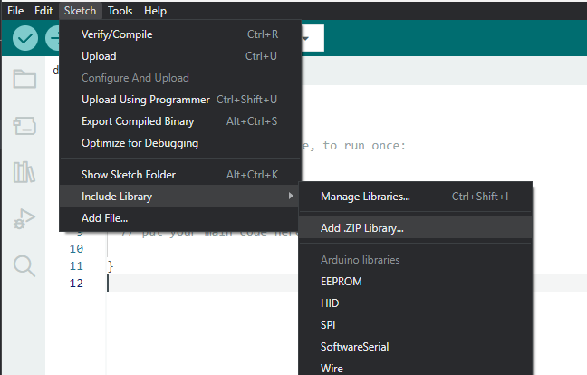
Here is a quick recap on how you can install Arduino libraries in the Arduino IDE 2.0.0+
- Download the library as a .zip
- In the Arduino IDE, go to Sketch → Include Library → Add .ZIP Library…
- Select the .zip of the library and click Open.
Make sure to #include the library header file so that
your
code compiles correctly.
| Timer Library | Download |
| TM1637 Library | Download |
Concepts
Measuring Time
We will record the time elapsed between a start and stop point. To do so requires a device within the ESP32 board called the… wait for it… timer! The ESP32 conveniently has four timers, only one of which we will need for measuring the time. Keeping it simple, we will use a library to interface with the timer and configure what is effectively a stopwatch program.
Using the Time Library
You can download the Time library here. Make sure to include the header file:
#include <Timer.h>
You will first instantiate a Timer object, declaring it in the global scope. This will control the timer device.
Timer timer;
Examine the table below for an overview of its member functions:
| Function | Summary |
|---|---|
timer.start();
|
Starts the timer |
timer.pause();
|
Pauses the timer; this is the PAUSED state |
timer.resume();
|
Resumes the timer when paused |
timer.stop();
|
Stops the timer; in this STOPPED state,
the next call to timer.stop()
resets the timer |
timer.read();
|
Returns the time elapsed since (in milliseconds) timer.start()
was called |
timer.state();
|
Returns the state of the timer as one of three constants: RUNNING, PAUSED, and STOPPED |
Interrupts
An interrupt request (IRQ) is a request to the ESP32's CPU to halt the currently executing code when an event occurs. After the request (or IRQ) is sent, the CPU will call another function to handle the event; it's called an interrupt handler or interrupt service routine (ISR). This is particularly useful in embedded systems for handling external interrupts, which are triggered by devices external to the CPU. For example, a button press may trigger an interrupt…
In a previous project, you may have implemented a program with pushbutton switches using a loop. Every iteration of the loop, you read the pushbutton's state, waiting to see if it was pressed. What an ordeal! Instead, we can use an interrupt to let the ESP32 know when the button is pressed. Then, the interrupt handler will perform whichever instructions follow the button press.
attachInterrupt
We will use a built-in ESP32 function to initialize an interrupt. A digital pin will serve as the line in which IRQs are sent. That same pin is where the external device, such as a pushbutton, should be connected.
attachInterrupt(interrupt, ISR, mode);
Let's discuss the parameters in the function above:
-
interruptis the desired number; it is not a pin number -
ISRis the name of the function which will be called as the interrupt handler -
modeconfigures the timing of the IRQ; the constants you may pass here are as follows:-
LOWtriggers the IRQ when the pin is at a LOW voltage -
CHANGEtriggers the IRQ when the pin when it changes value -
FALLINGtriggers the IRQ when the pin voltage changes from HIGH to LOW -
RISINGtriggers the IRQ when the pin voltage changes from LOW to HIGH
-
You will call this function in setup() for each interrupt you wish to initialize. But how do you find the corresponding interrupt
number of the digital pin?
digitalPinToInterrupt(pin);
Using the function above, simply pass the digital pin number and it will return the interrupt number.
The recommended approach to calling these functions is to perform them all in one line:
attachInterrupt(digitalPinToInterrupt(pin), ISR, mode);
Interrupt Handlers
After initializing an interrupt, we ought to define an interrupt handler. This will be like defining any other function, except there are no parameters and no return value.
Here is an example definition:
void interruptHandler()
{
Serial.println("The interrupt has been handled");
}
We will pass the name of this function, interruptHandler, as the argument ISR in attachInterrupt.
TM1637 7-Segment Display
If you have ever used a digital clock or watch, you have seen a seven-segment display! Each digit is composed of seven LEDs arranged into segments (as shown in the image below).
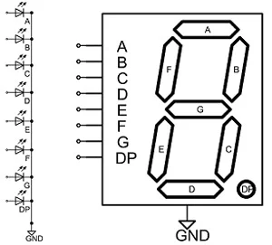
Activating a combination of the LEDs displays the desired number or character. It's very simple; however, the number of signal lines quickly grows for each additional digit. The TM1637 chip is designed to alleviate this exact problem. The IC interfaces with a 4-digit display and can be controlled via I2C protocol by the ESP32.
TM1637 Pinout Diagram
Below is a pinout of the TM1637. There are just four pins labeled on the side of the module.
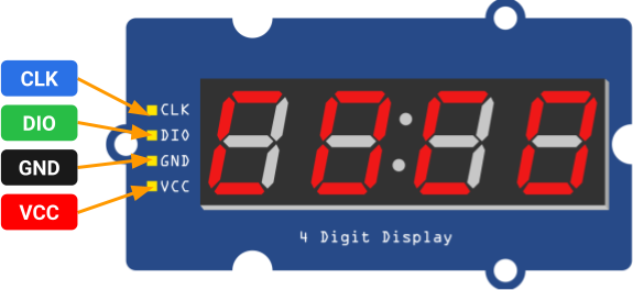
Once again, you may recognize the two I2C pins: DIO and CLK. Although their names differ from the traditional SDA and SCL, they serve the same purpose. These pins should be connected to any two digital pins on the ESP32 board.
Of course, we also need to power the module with the GND and VCC pins. Note that the VCC pin accepts 5V, so connect it to the 5V pin of the ESP32 board.
Using the TM1637 Library
Download the library here. Make sure to include the header file:
#include <TM1637Display.h>
First thing's first: Instantiate an object of the TM1637 class, declaring it in the global scope. Its two parameters are the digital pin numbers which have been connected to the module's DIO and CLK lines.
TM1637Display display(int CLK, int DIO);
You will call the display's clear() and setBrightness(int brightness) functions just once to
initialize the display. Place this
code in your setup() function.
display.clear();
display.setBrightness(7);
Note that the setBrightness(int brightness) function
changes the module's brightness and accepts a value between 0 (dim) and 7 (bright).
The next order of business is to display numbers! We will use the function below, which has three parameters of interest.
display.showNumberDecEx(int num, 0x40, bool leading_zero);
The first parameter, num, is the number that will be
displayed. The second parameter we will pass
0x40, which enables
the colon on the module. Lastly, leading_zero turns on
or off the leading zeroes on numbers which
are less than four
digits.
display.showNumberDecEx(123, 0x40, true); displays the
following to the module:
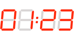
The digits populate right to left, and since leading_zero was set to true, the leftmost, unused
digit is a zero.
To learn more about what this library can do, check out the full documentation here.
Piezoelectric Buzzer
A piezoelectric buzzer is a component used to emit sound.
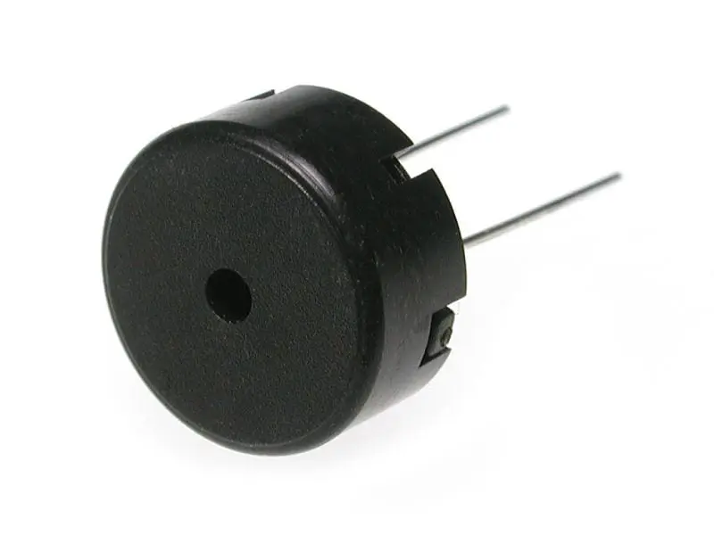
Piezo buzzers come in two varieties: active and passive. Active buzzers have a built-in oscillator with a set frequency that cannot be changed. Passive buzzers do not; they have to be fed an oscillating signal. We will use a passive piezo buzzer.
Using the Buzzer with ESP32
We will use a built-in Arduino IDE function to send a PWM signal of specific frequency to the piezo
buzzer. Instead of using
analogWrite, we will try tone, which allows you to set
the frequency and duration (in milliseconds)
of the PWM signal.
This is perfect for playing music notes!
tone(int pin, int frequency, long duration);
tone is a non-blocking function. The
program will not
pause for the duration of the note; it will continue to execute.
Here are some music notes translated to frequencies:
| Music Note | Frequency (Hz) |
|---|---|
| C5 | 523 |
| D5 | 587 |
| E5 | 659 |
| F5 | 698 |
| G5 | 783 |
Try it out! Play note C5 for 1 second with tone(6, 523, 1000); where the buzzer is connected to pin
21.
ESP32 Pinout Diagram
Thinking about using a pin you don't know what it does? Refer to the ESP32 Board pinout diagram.
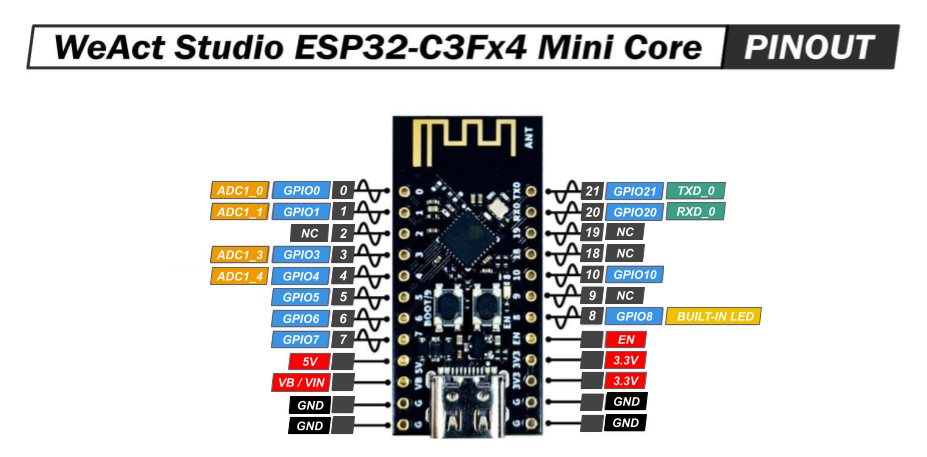 When trying to figure out what pin to use for your specific application/project, refer to the ESP32 Pinout diagram.
- NC stands for No Connect, and these pins should be left unconnected at all times.
- GPIO stands for a General Purpose Input/Output pin and can be used to send or read signals.
- ADC stands for analog to digital converter and it reads the input voltage and makes a digital number to represent that amount of voltage.
- TXD stands for transmitt data and can be used to transmitt data using a communication protocols.
- RXD stands for receive data and can be used to receive data using communication protocols.
- The ~ symbol represents pins that are PWM (Pulse Width Modulation) capable.
Requirements
For readers who are enrolled in the course: In order to receive full marks on your project submission, make sure it meets the following minimum requirements.
Toggle-able LED Circuit
- You must write a program in which the ESP32 board toggles the state of an LED (on pin 4) when a button is pressed.
-
The state of the LED must toggle only once for each button press
- Meaning… The LED should not flicker ON and OFF if the button is held down.
-
This program must be implemented with
attachInterrupt. -
No loops may be used (that includes the main
loop()). - The circuit must be built on a breadboard.
Digital Stopwatch
- You must build a digital stopwatch with two buttons, the TM1637, and a piezo buzzer.
-
One button one serves as a “Start/Pause/Resume” button.
- When this button is first pressed, the stopwatch begins.
- A second press of this button should pause the stopwatch. Another press should resume it.
-
The second button one serves as a “Stop” button.
- When this button is pressed, the stopwatch stops, and the display freezes on the time elapsed. The next press of the “Start/Pause/Resume” button resets the display to zero stopwatch and starts the stopwatch.
-
When the stopwatch is active, the TM1637 must display the number of minutes and seconds elapsed.
- The colon must be displayed
- The two digits to the left of the colon should display the number of minutes elapsed.
- The two digits to the right elapsed should display the number of seconds elapsed in the current minute.
- Each time a button is pressed, the buzzer must play at least one note.
- Each time a minute elapses, the buzzer must play at least one note.
-
Buttons must be implemented with
attachInterrupt. -
You may use the main
loop()only for time conversion, updating the display, and sounding the buzzer. - The circuit must be built on a breadboard.
Parts
| Part Name | Qty |
|---|---|
| ESP32 | 1 |
| Breadboard | 1 |
| TM1637, 7 Segment Display | 1 |
| Switch, Tactile | 2 |
| Piezo Buzzer, 1.5V | 1 |
| Dupont Jumper Wire (Male-to-Female) | 4 |
Schematics


Instructions
Checkpoint 1
-
Build the circuit in Schematic A (Toggle-able LED Circuit) on your breadboard.
Connect and toggle an LED to the ESP32's 4 pin.Don't forget to use INPUT_PULLUP when setting the pinmode of the pushbutton pin.
- Upload your sketch to the board, and verify that the system executes as expected.
Checkpoint 2
- Build the circuit in Schematic B (Digital Stopwatch) on your breadboard.
- Upload your sketch to the ESP32, and verify that the program executes as expected.
Deliverables (Enrolled Students Only)
Students enrolled in the course must submit the following deliverables to the corresponding Canvas course assignment.
Place the following files in a single folder:
-
Video of the Digital stopwatch ESP32 board
This video should include the TM1637, two pushbuttons, piezo buzzer and ESP32 correctly wired together.Demonstrate that seconds and minutes are properly displayed by the stopwatch. Show the display update from 50 seconds to 1 minute and 10 seconds elapsed.Start, pause, resume, and stop the stopwatch in the video. Then, start the stopwatch one more time to demonstrate all features of the stopwatch.
-
Digital stopwatch Arduino sketch file
This file should include all of the code you have written for the ESP32 acting as the transmitter. Name it “ops_project7.ino".
Compress the folder to a zip file and rename the file using the format “ops_project7_lastname_firstname.zip” Then, submit the zip file to the Project 6 Canvas assignment.