Capstone Project
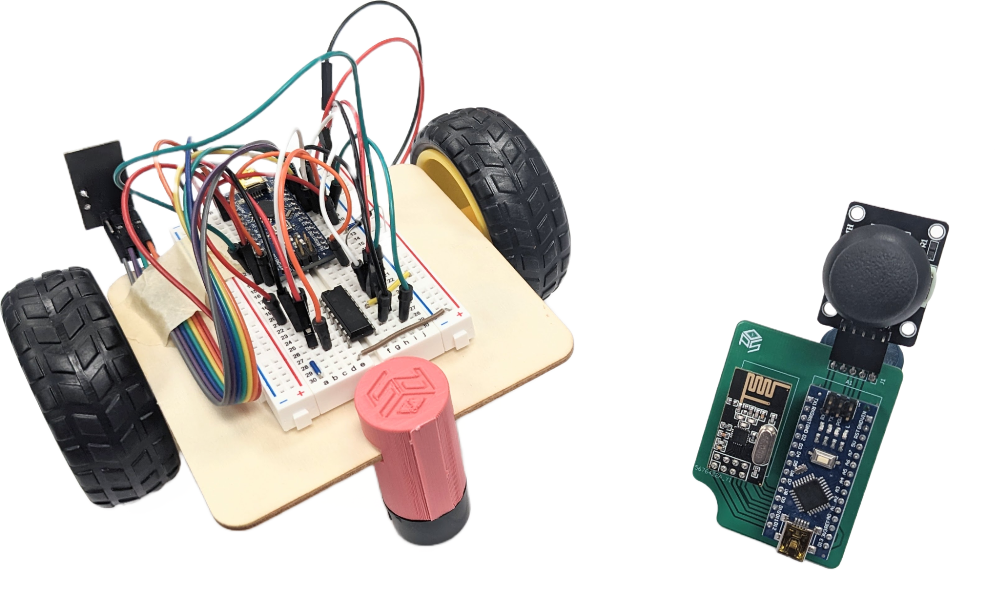
RC Rover
By Patrick Cabanban
Introduction
In this final project, you will create a remote-controlled rover. First, you will design a PCB layout for the remote control and send the CAD files for manufacturing. Then, you will assemble and program the rover. The last step is to solder the components to your custom PCB upon its arrival. The Capstone will require knowledge of everything taught up until this point. From circuit design to soldering, you will have free reign in building this project. It will only need to meet the base requirements; the rest is up to you.
Schedule
| Week | Suggested Activity | Workshop |
|---|---|---|
| 1 | Capstone PCB Design (Due April 5th, 2026 at 11:59 PM) | |
| 2 | Rover Assembly | Capstone Rover Assembly: Workshops on Thursday, April 9th, 2:30-3:30 in ICS259 or Friday, April 10th, 5-6 in EH2430 |
| 3 | Rover Assembly | |
| 4 | PCB Assembly | Capstone PCB Assembly |
| 5 | PCB Assembly | |
| 6 | Program Remote Control and Rover | Capstone Programming |
| 7 | Program Remote Control and Rover | |
| 8 | Suggested Submission Deadline | |
| 9 | Continue Working If You Haven't Finished | |
| 10 | OFFICIAL Capstone Project Submission Deadline: June 5th, 2026 at 11:59PM |
Installing KiCad
To complete this project, you will download the PCB design software KiCad (the latest version).
| Windows | Download |
| Mac | Download |
- Download the installer from the link appropriate to your OS.
-
Launch the installer (we use a previous version here but use the latest version). Click Next.
-
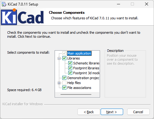
When the Choose Components dialog appears, make sure all but the “Help files”
components are selected. Then, click Next.
-
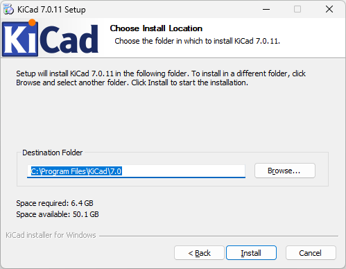
Select the Install Location. The default setting is usually acceptable. Then,
click Install.
- The installation is complete! The fun starts now.
Concepts
Analog Joystick
The remote control will accept input via an analog joystick. The component outputs analog signals that the ESP32 will read and process. Much like a console controller, the joystick has two axes, horizontal and vertical. The degree to which the joystick has pivoted along these axes determines the output of its data lines.
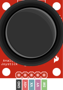
Joystick Pinout
To the left is the pinout of the joystick. The GND and +5V pins power
the Joystick.
Make sure they are connected appropriately to the ESP32.
The next two pins are VX and VY, which
carry analog signals for
the horizontal and vertical position of the joystick, respectively. These pins must be connected to
analog pins on the ESP32.
The last pin is SW. The joystick may act as a button/switch,
the digital signal of which
is carried by SW. This pin should be connected to a digital pin on
the ESP32.
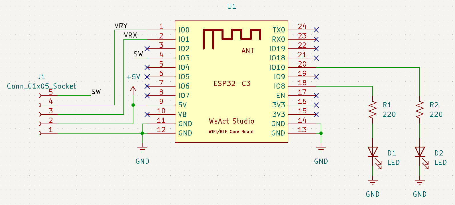
Wiring the Joystick to the ESP32
The following connections are recommended, so the PCB design procedure is easier to follow. In the end, you can wire the joystick however you like as long as the PCB layout reflects your design choices.
| Joystick Pins | ESP32 Pins |
|---|---|
| GND | GND |
| +5V | 5V |
| VX | 1 |
| VY | 0 |
| SW | 3 |
Pull-Up Resistors
Suppose you use a digital input pin on the ESP32, but it’s not connected to anything. Is the
state of the pin HIGH or LOW?
For it to be HIGH, the pin would need to be connected to the VCC power source. For the state to be
LOW, the pin would need to be
connected to GND. When the state is indeterminate like this, the pin is said to have a floating
signal, which we should avoid.
The solution is what we call a pull-up resistor. The input pin is connected to a high-value
resistor R1 whose other terminal
is attached to VCC (as depicted below).
The intent is to set the input pin to the HIGH voltage. We often use a 10kΩ resistor to do so
because it drives the current down low
(recall V=IR). Now, the input pin has an effective resistance in the range of 100 MΩ. That’s right:
mega-ohms.
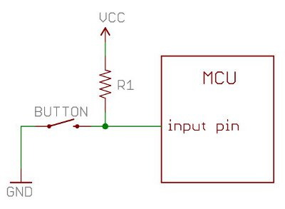
The resistance of the pull-up resistor R1 and effective resistance of the input pin divide the voltage VCC such that the voltage at the input pin is equal to VCC (HIGH).
Now, let’s introduce the button: one terminal attached to the input pin and the other GND.
When the button is pressed, the voltage at the input pin is shorted to GND (LOW).
With this circuit, the input pin will either be VCC or GND (HIGH or LOW).
When you use a button or, in our case, the SW pin of the joystick,
you should use a pull-up resistor.
Instead of building an external circuit, you can use an internal pull-up resistor in the
ESP32. You may do so by setting
the pin mode as follows:
pinMode(pin, INPUT_PULLUP);
There are also pull-down resistors, which we will not discuss here.
L293D Quadruple Half-H Driver
We will use an L293D chip to drive the two DC motors of the rover. To power a DC motor, all we need is to apply a voltage, but to change the direction the motor spins, we must do a little bit more. We apply the opposite voltage to change the direction of current passing through the motor. This changes the direction the motor spins as well…
The L293D IC makes it possible to drive two motors bidirectionally, and it does so by controlling the direction of current flow through each motor.
Reading the Big Scary Manual
This time around, we will not thoroughly discuss the driver’s operation. You will have to read
the datasheet, and figure it out yourself.
L293D Quadruple Half-H Driver Datasheet.pdf
Skim through the datasheet to familiarize yourself with the documentation. Some items you may
recognize but the vast majority you may not.
This is okay!
Pay close attention to pages 3, 7, and 11-12. These pages will help you the most in
understanding the functions of the IC.
As you read, here are some things to note:
- The documentation refers to both the L293 and L293D, only the latter of which we will use. This version of the chip contains flyback diodes.
- Of the several system examples, we will use the Bidirectional DC Motor Control.
- The term “logic” refers to the binary HIGH and LOW output of the ESP32 digital pins.
L293D Pinout
Below you will find a pinout of the chip. Initially, it will seem overwhelming, but it will make more sense as you navigate the datasheet.
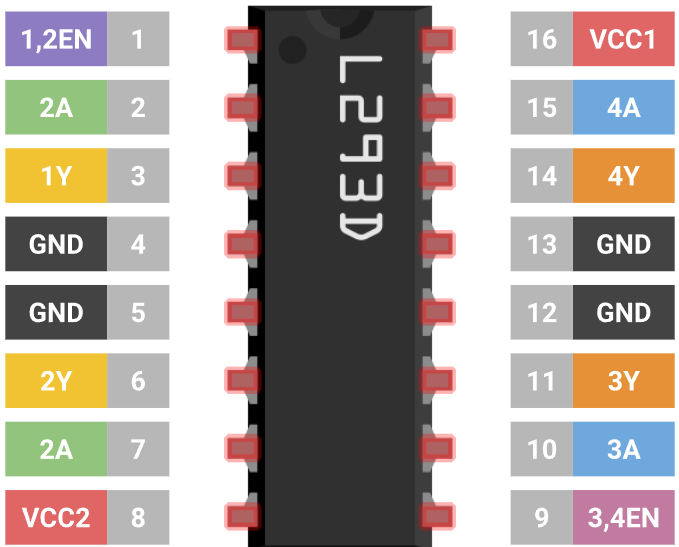
Ensure that the ESP32 board and L293D share a ground connection.
As you will learn in the datasheet, 1EN and 2EN are enable pins, which you will
need to set to HIGH to control the driver channels. Note that if you apply a PWM signal to these
pins, you can control the speed of their respective
channels.
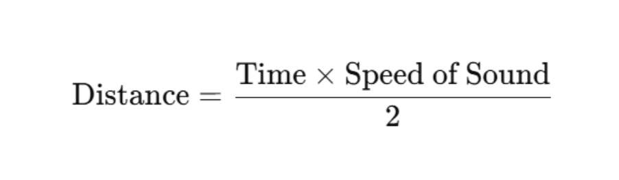
Ultrasonic Sensor
The ultrasonic sensor module (commonly the HC-SR04 )is a distance-measuring device widely used in embedded systems. It works by emitting an ultrasonic sound wave (at around 40 kHz) from its trigger (TRIG) pin and then listening for the echo reflected off nearby objects using its echo (ECHO) pin. The time it takes for the sound wave to return is measured by the microcontroller, which is used to calculate the distance using the formula:
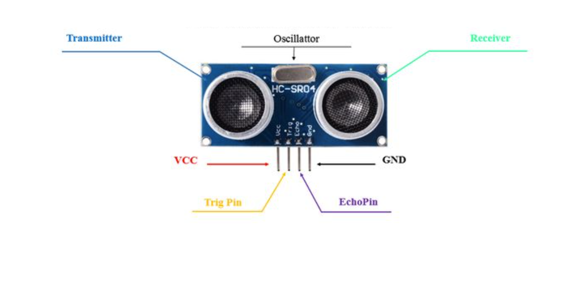
A demo of using our provided ultrasonic sensor is found below:
-
Trig pinis in charge of sending a signal to the ultrasonic sensor to emit a burst of ultrasonic sound waves -
Echo pinis in charge of being pulled to HIGH for the same duration equal to the time it takes the ultrasonic pulse to reach a surface and return to the sensor. -
pulseInmeasures how long the ECHO pin was set high -
Delayensures that the trig pulse is a burst
const int trigPin = 3;
const int echoPin = 4;

void setup() {
  Serial.begin(115200);
  pinMode(trigPin, OUTPUT);
  pinMode(echoPin, INPUT);
}


void loop() {
	// Trigger pulse
  digitalWrite(trigPin, LOW);
  delayMicroseconds(100);
  digitalWrite(trigPin, HIGH);
  delayMicroseconds(100);
  digitalWrite(trigPin, LOW);

  long duration = pulseIn(echoPin, HIGH);  // Takes measurement of pulse in microseconds
  long distance = duration / 58.0;         // conversion to cm
  Serial.println(“Distance: “ + distance);
  delay(1000);
}
Note that the material and the angle of the object the wave is bouncing off matter for how effectively the echo pin can receive the signal. Materials like sponges or even your hand aren’t great at reflecting the waves.
Using it with ESP32
The ultrasonic sensor is actually rated for 5V, which means it is advised to use a voltage divider network on the GPIO pins that it connects to. This is because constant 5V exposure to the ESP32 GPIO pins, which are rated for 3.3V, will possibly damage the module. Below, you will find the schematic displaying the resistor values and configuration you must implement to optimize the ultrasonic sensor’s usage.
WiFi
WiFi is the most popular choice for wireless communication between devices. It uses radio waves to “connect” devices, allowing them to communicate. While we won’t be using an actual WiFi network, we will use the ESP32’s communication protocol ESP-NOW, which uses the ESP32’s built-in WiFi module.
Here’s how we’ll transmit data: One ESP32’s WiFi module will wirelessly transmit messages to another ESP32’s WiFi module using the ESP-NOW protocol. We won’t dive into the details of how ESP-NOW works, but we will cover the concept of how radio waves are emitted.
Radio Frequency Bands and Channels
Remember that the WiFi modules send information over radio waves, just like our mobile phones, satellites, and WiFi. But how do the radio waves emitted by a satellite not interfere with the radio waves of a WiFi router or iPhone? Let’s explain: Each signal belongs to a frequency band or range of contiguous frequencies specified by the International Telecommunication Union (ITU).
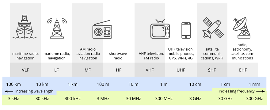
WiFi exists in 2.4 GHz,5 GHz and 6 GHz bands. These bands are further divided into channels.
For example, 2.4 GHz WiFi 14 channels, each with a different radio frequency within the larger frequency band. FM radio stations are assigned to unique channels, which is why you normally don’t hear Taylor Swift overlaid with the latest stock market report. WiFi networks close together are assigned to different channels so they do not interfere with each other. For instance, if you and your next-door neighbor set your WiFi networks to the same channel, the networks would interfere, slowing down your internet speeds.
If multiple radio signals were to exist on the same frequency, a collision would occur. This is why the ITU takes special care to regulating the radio spectrum.
The ESP-NOW communication protocol operates on a 2.4 GHz frequency band, which it shares with many WiFi networks. However, ESP-NOW is not a WiFi network itself; it is a different wireless communication that uses an ESP32’s WiFi module to directly communicate with another ESP32. While WiFi uses an access point to establish a connection between two devices, ESP-NOW identifies another ESP32 board by its MAC address and uses the ESP32 WiFi module to directly transmit data to that receiver address.
Using the WiFi Library
Download the library
here .
Make sure to include the header file:
#include <WiFiConfig.h>
You need to determine the MAC address of the receiver ESP32 board. Run this sketch code on your receiver ESP32. The serial monitor should show the MAC address as a series of hexadecimal numbers separated by colons.
Example address: 34:b7:da:f6:3e:78.
#include <WiFi.h>
#include <esp_wifi.h>

void readMacAddress(){
	uint8_t baseMac[6];
	esp_err_t ret = esp_wifi_get_mac(WIFI_IF_STA, baseMac);
	if (ret == ESP_OK) {
	Serial.printf("%02x:%02x:%02x:%02x:%02x:%02x\n",
					baseMac[0], baseMac[1], baseMac[2],
					baseMac[3], baseMac[4], baseMac[5]);
	} else {
	Serial.println("Failed to read MAC address");
	}
}

void setup(){
	Serial.begin(115200);
	WiFi.mode(WIFI_STA);
	WiFi.STA.begin();
	Serial.print("[DEFAULT] ESP32 Board MAC Address: ");
	readMacAddress();
}

void loop(){
	Serial.print("[DEFAULT] ESP32 Board MAC Address: ");
	readMacAddress();
}
Next, create an array to store the receiver ESP32’s MAC address. Each hexadecimal number should be one entry in the array, with the prefix 0x to specify that the number is in hexadecimal. So for our example address 34:b7:da:f6:3e:78, we would initialize the array below:
uint8_t receiverAddress[] = {0x34, 0xB7, 0xDA, 0xF6, 0x3E, 0x78}
The next step is to put your ESP32 board in WiFi mode to prepare the onboard WiFi module for communication and start the ESP-NOW protocol. Place this code in your setup() function.
wifi_setup();
You will set the receiver ESP32 as the transmitting board’s “peer” by passing the receiver board’s
MAC address into the peer_setup() function. This ensures ESP-NOW knows which board it is transmitting to.
peer_setup(receiverAddress);
Let’s move on to the code that would appear in the main() loop. This is where RemoteData messages
will be read and written (transmitted and received). To facilitate the data transfer, you are provided with a special container RemoteData with three member variables that are initialized as follows. Note that these variables are uint8_t type (unsigned 8-bit integers 0-255).
RemoteData data;
data.vx = 77;
data.vy = 89;
data.sw = 3;
To send data to the other ESP32, use the send_data() function, passing both the receiver
address and RemoteData container as arguments
send_data(receiverAddress, data);
To receive data, you need to configure your other ESP32 as the receiver in its sketch.
Create a global RemoteData variable (for example, report) and use the set_data_receiver() function,
passing in the address of the RemoteData container as an argument.
set_data_receiver(&data);
This code ensures that whenever the ESP32 receives data, it will automatically update your RemoteData container with the transmitted values. &data is the memory location that contains your RemoteData, which is needed to update the values.
Here’s an example of all the code put together.
Do not blindly copy-paste the sample code to your project deliverables. You will need to determine which functions to use in your individual transmitter and receiver sketches.
#include <WiFiConfig.h>
//Find the mac address of your receiver ESP32 first, then enter it in here:
uint8_t receiverAddress[] = {0x34, 0xB7, 0xDA, 0xF6, 0x3E, 0x78};

RemoteData data;      // global initialization of RemoteData


void setup()
{
  Serial.begin(115200);                // Serial setup
  wifi_setup();                      // start wifi mode and ESP-NOW
  peer_setup(receiverAddress);       // configure receiving address
  set_data_receiver(&data);      // configure the receiver ESP32 to update data's values upon reception
}

void loop()
{
  data.vx = 34;
  data.vy = 70;
  data.sw = 0;


  send_data(receiverAddress, data);       // send the data
  Serial.print("VX: ");              // Print VX
  Serial.println(data.vx);

  delay(1000);
}
ESP32 Pinout Diagram
Thinking about using a pin you don't know what it does? Refer to the ESP32 Board pinout diagram.
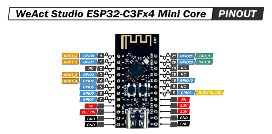 When trying to figure out what pin to use for your specific application/project, refer to the ESP32 Pinout diagram.
- NC stands for No Connect, and these pins should be left unconnected at all times.
- GPIO stands for a General Purpose Input/Output pin and can be used to send or read signals.
- ADC stands for analog to digital converter and it reads the input voltage and makes a digital number to represent that amount of voltage.
- TXD stands for transmitt data and can be used to transmitt data using a communication protocols.
- RXD stands for receive data and can be used to receive data using communication protocols.
- The ~ symbol represents pins that are PWM (Pulse Width Modulation) capable.
Requirements
In order to receive full marks on your project submission, make sure it meets the following requirements. Beyond this, you can do whatever you like.
- You must build a rover and a remote control.
- The rover must be controlled wirelessly via the remote control.
- The remote control should use a joystick for user input.
- A user should be able to intuitively use the joystick to control the rover. This means that pivoting the joystick left should move the rover left, not backward.
- The remote control should feature two LEDS: A green one that turns on when the rover is moving and a red one that turns on when the rover is not moving.
-
You must design a PCB for the remote control.
- The PCB must adhere to the provided manufacturer constraints.
- The PCB must be less than 100x100mm in size.
- When the joystick is clicked, the rover should switch between remote controlled mode and autonomous mode.
- In autonomous mode, the rover should be able to move without user input and navigate obstacles according to ultrasonic sensor readings.
- The rover must be able to move forward, backward, left, and right in response to commands sent by the remote.
- Lastly, the rover must be stable and reliable. There should be no spontaneous movement, no wireless connection issues, and absolutely no sparks.
Parts
| Part Name | Qty |
|---|---|
| Breadboard | 1 |
| 9V Battery | 1 |
| JST PH2.0 Female Connector | 1 |
| JST PH2.0 Snap 9V Battery Male Connector | 1 |
| Ultrasonic Sensor | 1 |
| Ultrasonic Sensor Mount | 1 |
| Gearbox Motor | 2 |
| Wheel | 2 |
| Ball Caster | 1 |
| Metal Ball | 1 |
| Long Screw | 2 |
| Hex Nut | 2 |
| Ball Caster Chassis Grip | 1 |
| 4”x4” Wood Plate (Chassis) | 1 |
| 9V Battery Holder | 1 |
| L293D Quadruple Half-H Driver IC | 1 |
| ESP32 | 2 |
| USB-A to USB-C Cable | 1 |
| Analog Joystick | 1 |
| 1x5 Pin Female Header(Bent) | 1 |
| 1x12 Pin Female Header | 2 |
| LED | 2 |
| Resistor, 220Ω | 2 |
| Jumper Wire | ? |
| Positive Attitude | 1 |
Schematics
Instructions
PCB Assembly
- Place the headers on your newly manufactured PCB. Remember that you are not soldering the actual components to the board, just the headers.
- Solder the headers to the PCB.
- Place the components on the headers. Viola! You are done.
Rover Assembly
You may customize the rover however you like, but it does need to work. Just in case, we offer instructions on how to build it.
-
Collect the listed components, all of which are displayed below:
- Breadboard
- 9V Battery Holder
- Ultrasonic Sensor
- Ultrasonic Sensor Mount
- 9V Battery
- 9V Battery Snap Connector with Dupont Terminals or JST Female Snap Connector with Male JST Header
-
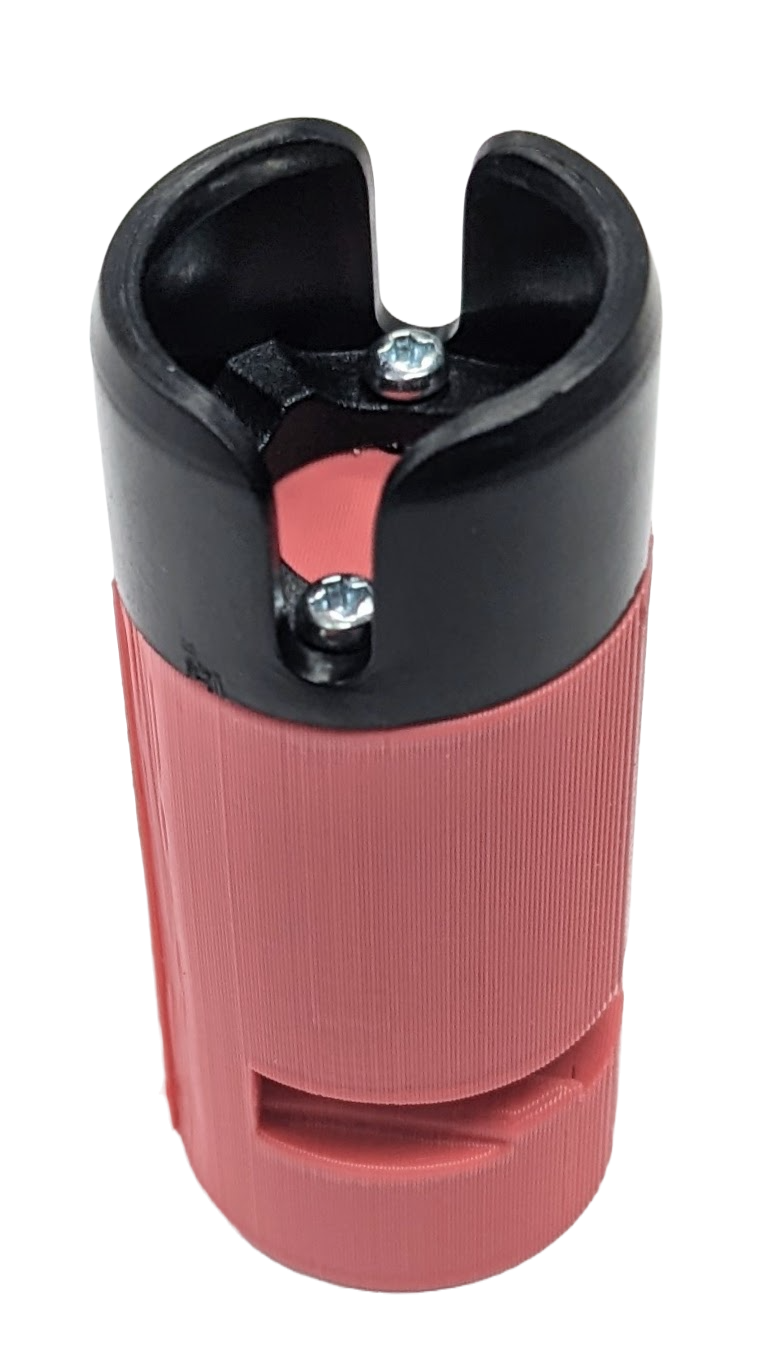
Ball Caster Components (You may have a pre-assembled ball caster components in your
kit…
In which case, ignore the following.)
- Ball Caster Chassis Grip
- Ball Caster
- Metal Ball
- Long Screws (2)
- Hex Nuts (2)
- Wheels (2)
- 4”x4” Wood Plate (Chassis)
- Gearbox Motors (2)
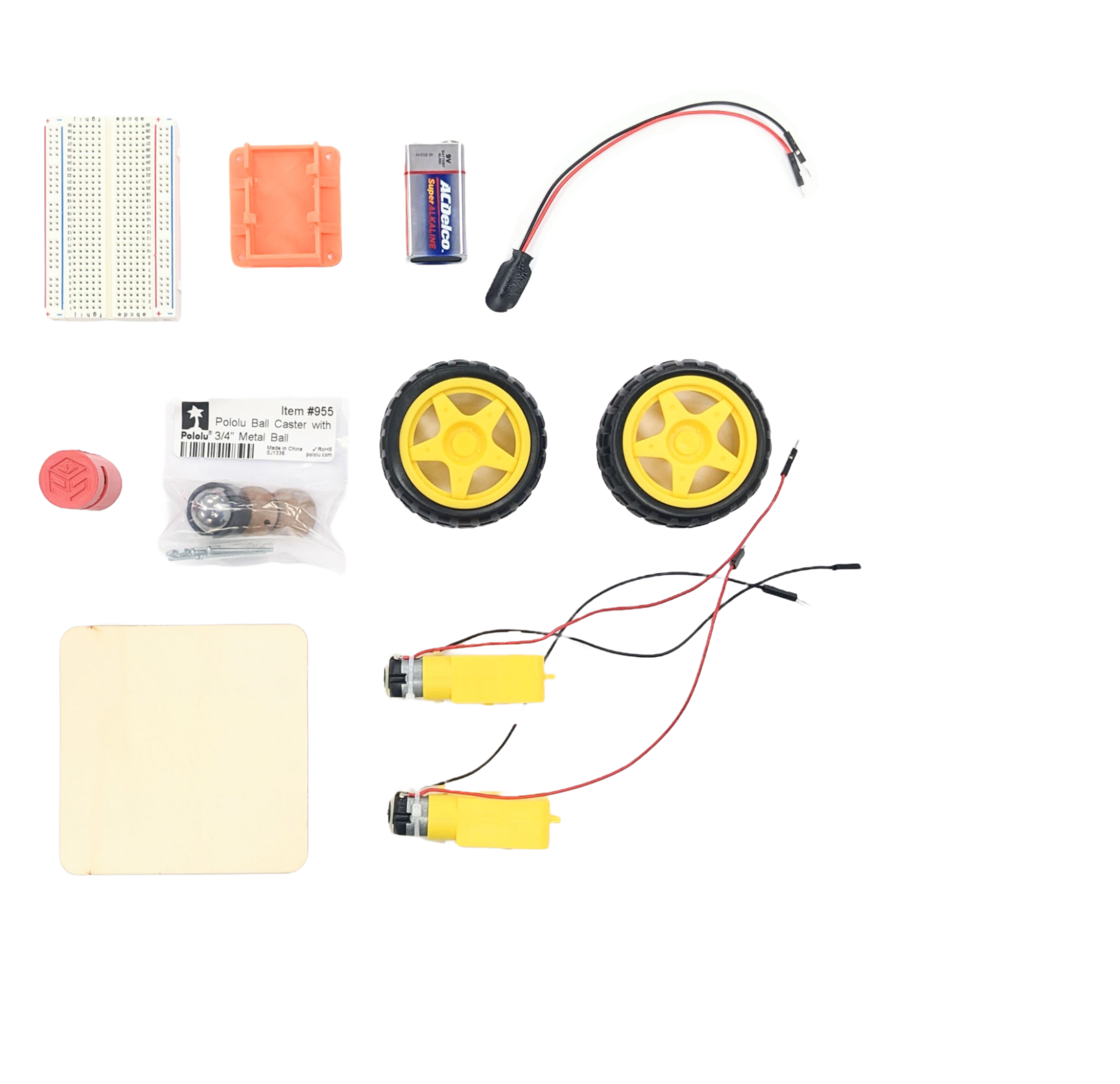
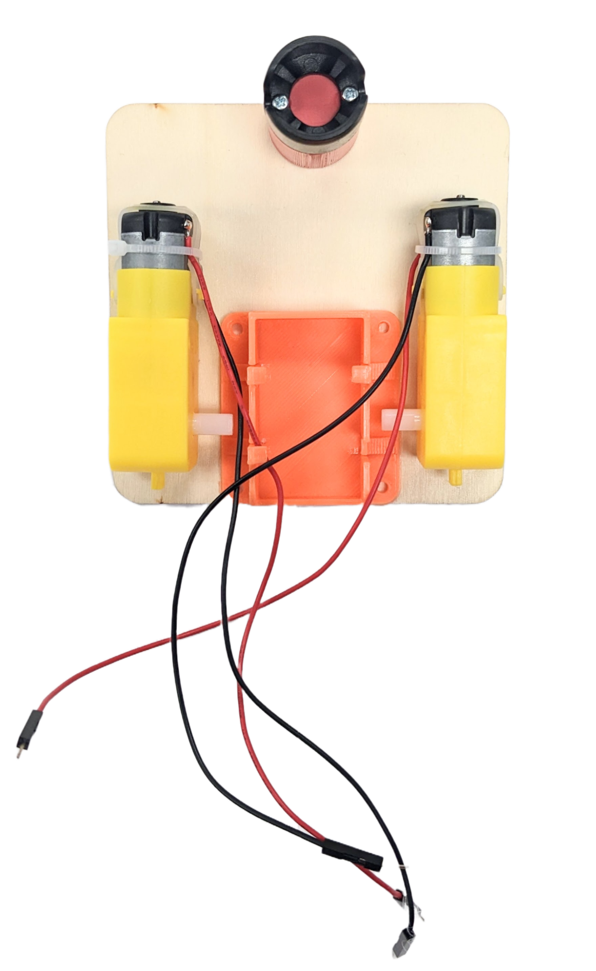
-
Adhere the 9V battery holder to one face of the wood plate. Center the battery holder along
the edge of the plate.
Make sure the open side of the battery holder is on the edge of the wood plate.
Hot Tip: Use a glue gun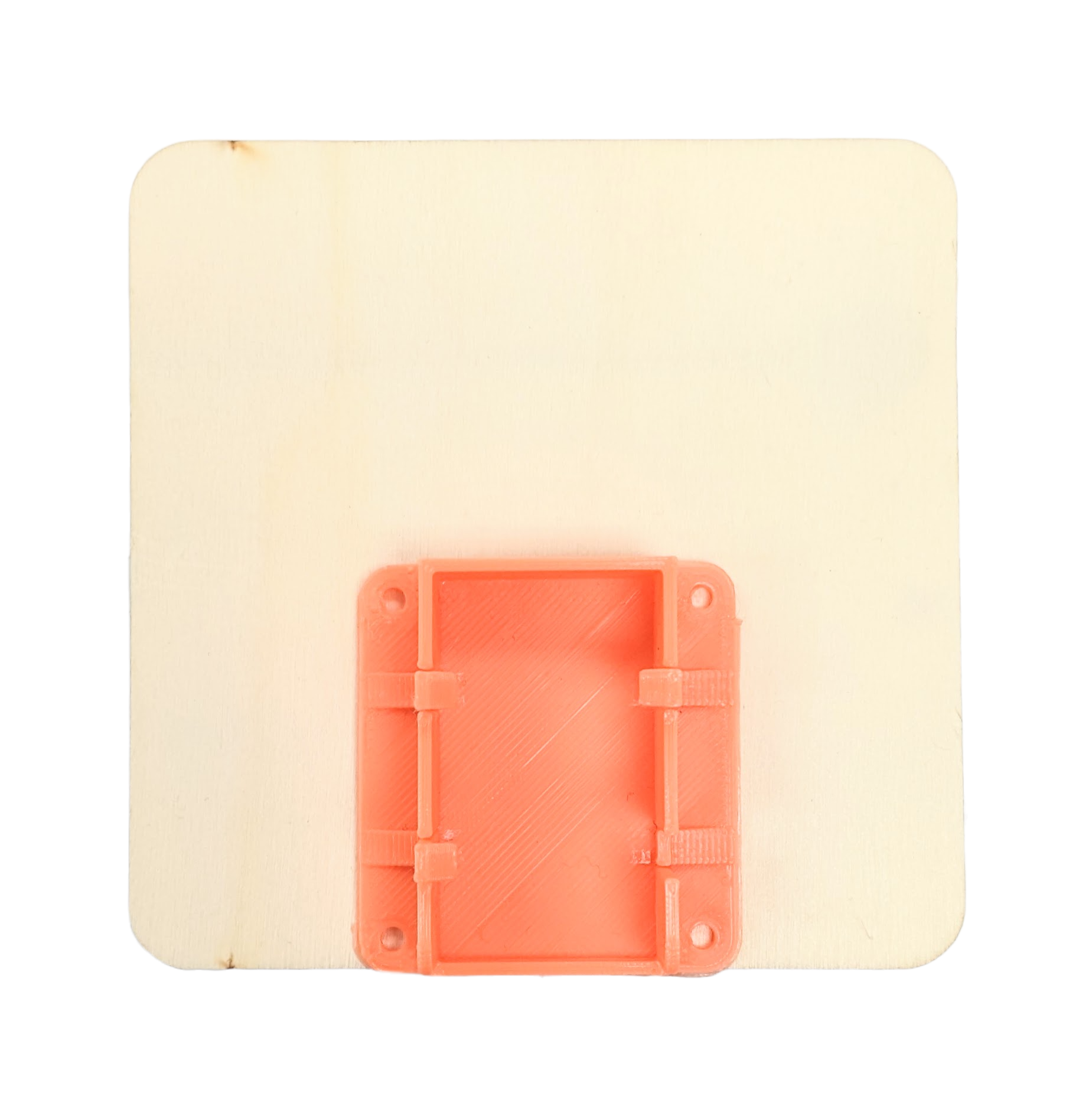
-
Adhere the two gearbox motors to the wood plate so that they sit on either side of the
battery holder.
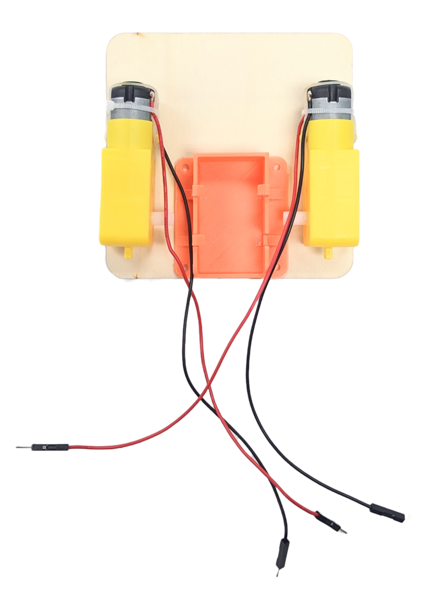
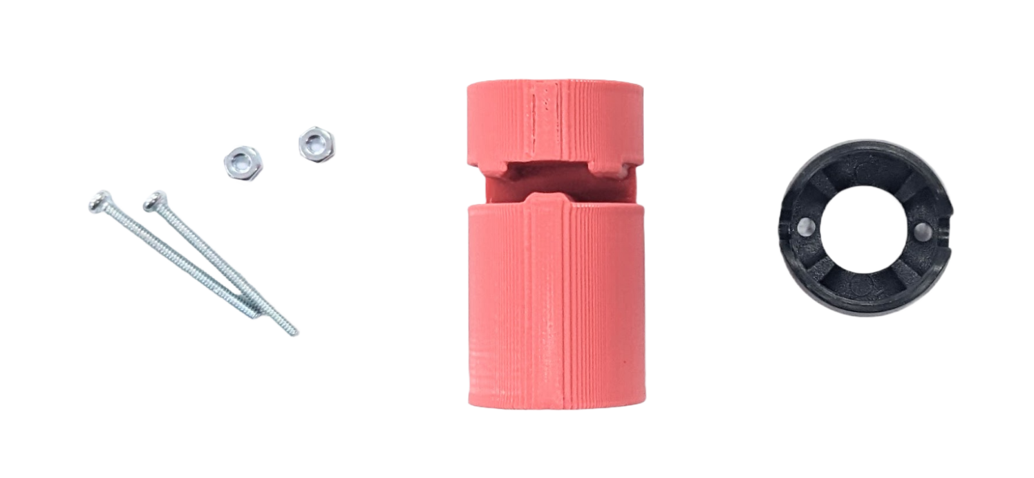
-
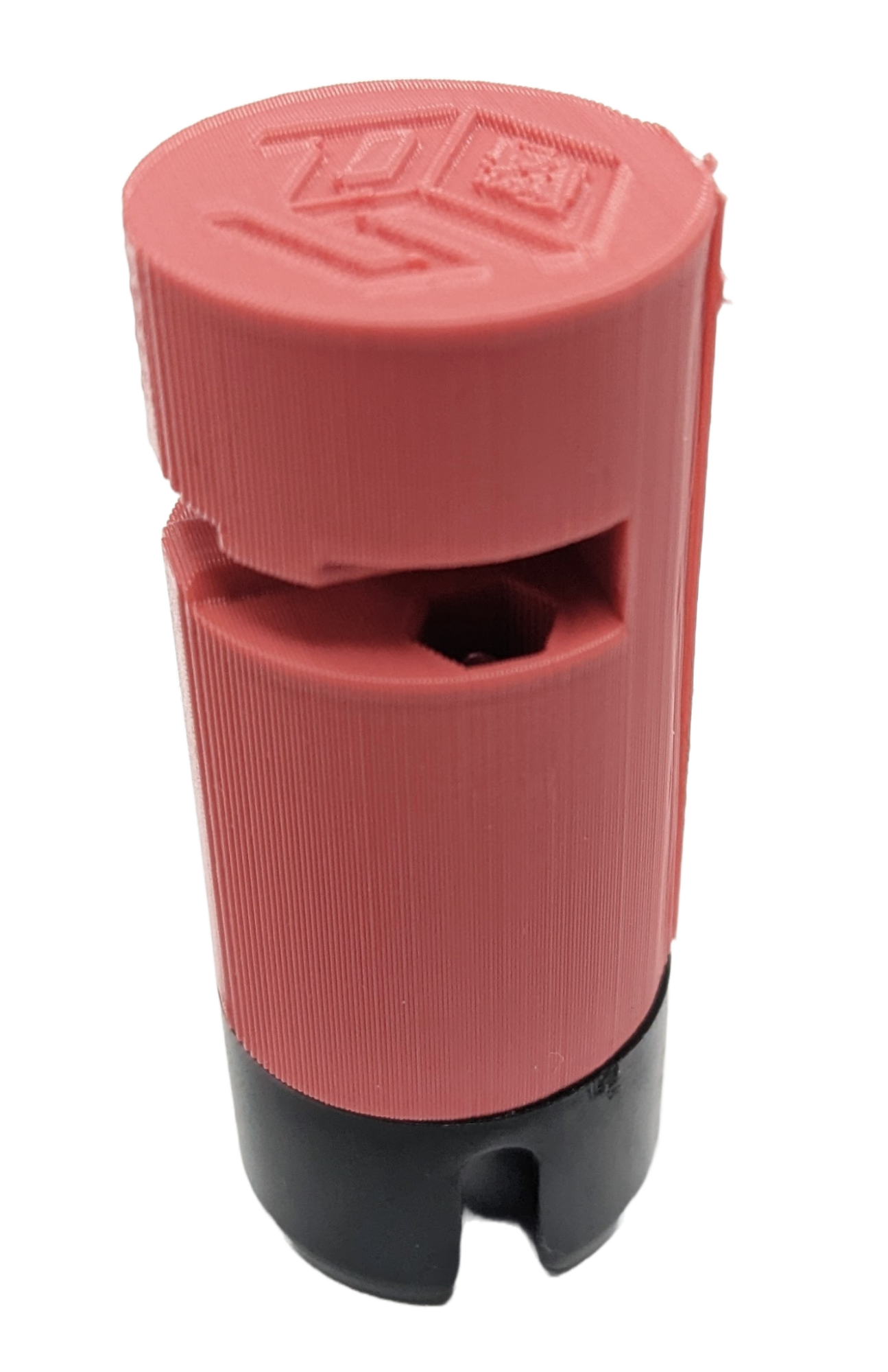
If you have pre-assembled ball caster components, ignore this step: Using the long
screws and hex nuts, fasten
the black ball caster to the chassis grip. To do so…
- Place the hex nuts in the hexagonal hole inside the clip.
- Feed the screws through the caster’s holes and the holes at the bottom of the grip.
- Tighten the screws until the hex nuts “catch” them and the ball caster is tightly bound.
-
Clip the chassis grip to the edge of the plate opposite to the battery holder. Center align
the chassis grip
along the edge as well.
-
Attach the wheels to the gearbox motors, the metal ball to the caster, and the 9V battery to
the battery holder.
Note that the battery slides into the holder as shown below.
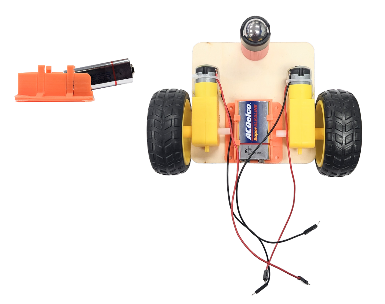
-
Attach the wheels to the gearbox motors, the metal ball to the caster, and the 9V battery to
the battery holder.
Note that the battery slides into the holder as shown below.
-
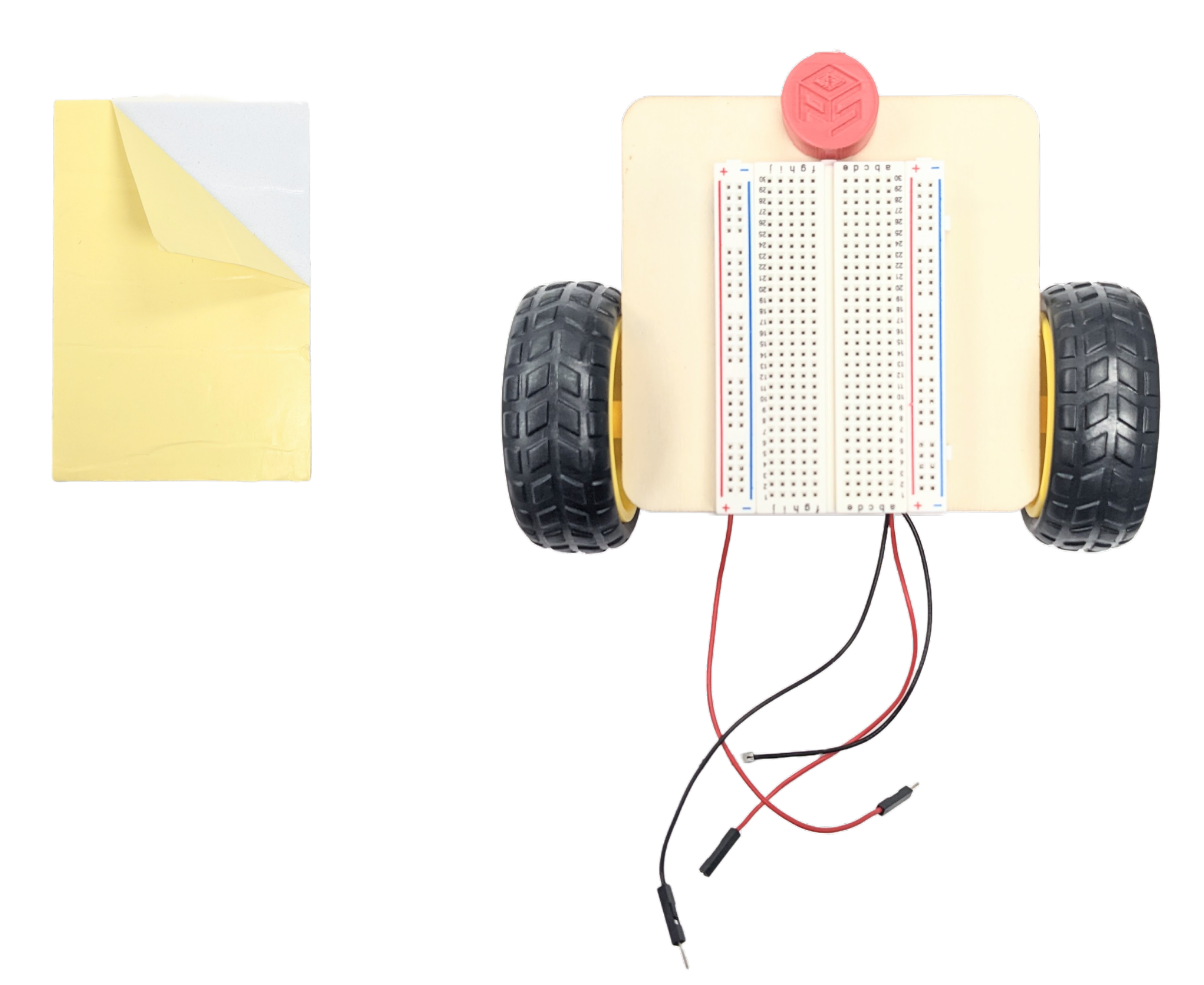
The final step is to place and wire the electrical components on the breadboard. Remember
that there is no
schematic. You have to design the circuit yourself.
Try drawing up your own schematic on Tinkercad first. You can use all the same components and even simulate your circuit with code!
If you get stuck, ask questions.
Programming
How you write the code is all up to you. Just make sure there are two files, one for the rover and one for the remote control. As a final suggestion, look back at your old project submissions and reuse applicable code.
Deliverables
PCB Design
Compress the KiCad project folder as a .zip. It must contain the following:
- KiCad Project File (.kicad_pro)
- KiCad PCB File (.kicad_pcb)
- KiCad Schematic File (.kicad_sch)
Then, submit the .zip file to the Capstone PCB Design Canvas assignment. Make sure that the file name follows the format: “capstone_firstname_lastname.zip”
Final Submission
Place the following files in a single folder:
-
Video of your rover and the remote control
The video should include a demonstration of the rover moving forward, backward, left, and right. Make sure to show the remote as well. Then, switch to autonomous mode and show the rover moving, avoiding obstacles it encounters.
-
Rover ESP32 sketch file
This file should include all of the code you have written for the rover. Name it “capstone_rover.ino”.
-
Remote Control ESP32 sketch file
This file should include all of the code you have written for the remote control. Name it “capstone_remote.ino”.
Compress the folder to a zip file and rename the file using the format: “capstone_final_firstname_lastname.zip”. Then, submit the .zip file to the Capstone Final Submission Canvas assignment.